4L60E Repair
Guide - Disassembly 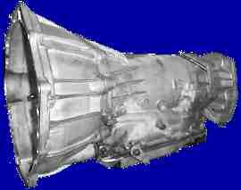
TRANSMISSION
DISASSEMBLY
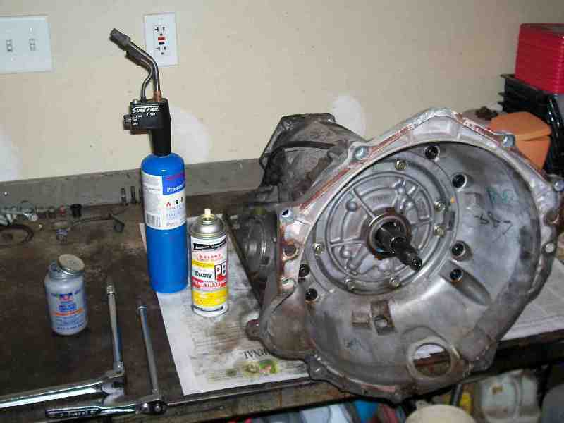
Place the transmission on a sturdy workbench.
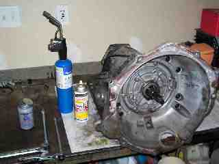
Remove the
transmission
mounting bell housing. This is not a task for a bargain
tool. The
Torx fasteners used to assemble the bell to the trans have a T-45
recess, and are not only torqued to a high level but have had adhesive
applied. Beyond that, they may have suffered seizure and galling
upon
installation or since, and will require significant torque to break
free. Use a good quality, undamaged Torx driver bit. Penetrating
oil
applied well in advance and heat on the case areas surrounding the
bolts will make the job much easier. This one step can turn the
project into a nightmare if not done successfully.
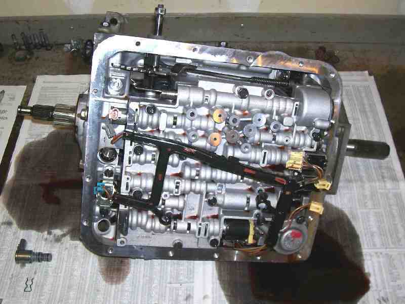
Remove
the transmission oil pan and filter. 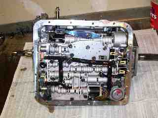

Remove
the wire harness and main electrical connector socket. The socket
has
four locking tabs which need to be compressed inward to allow the
socket to be pushed into the transmission.
Remove
the TCC pressure signal solenoid (if equipped) retaining clip, then
slide the
solenoid from the valve body.
Remove
the TCC solenoid retaining bolts and slide the TCC solenoid valve out
of the pump body.
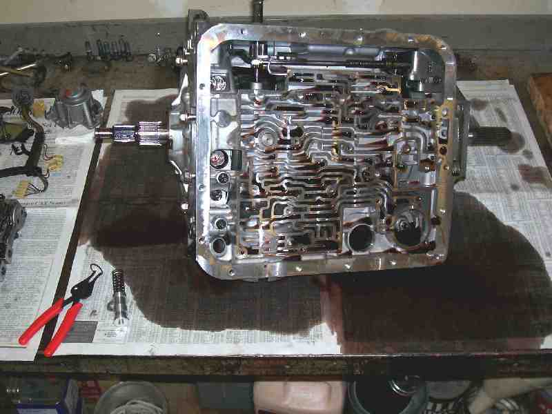
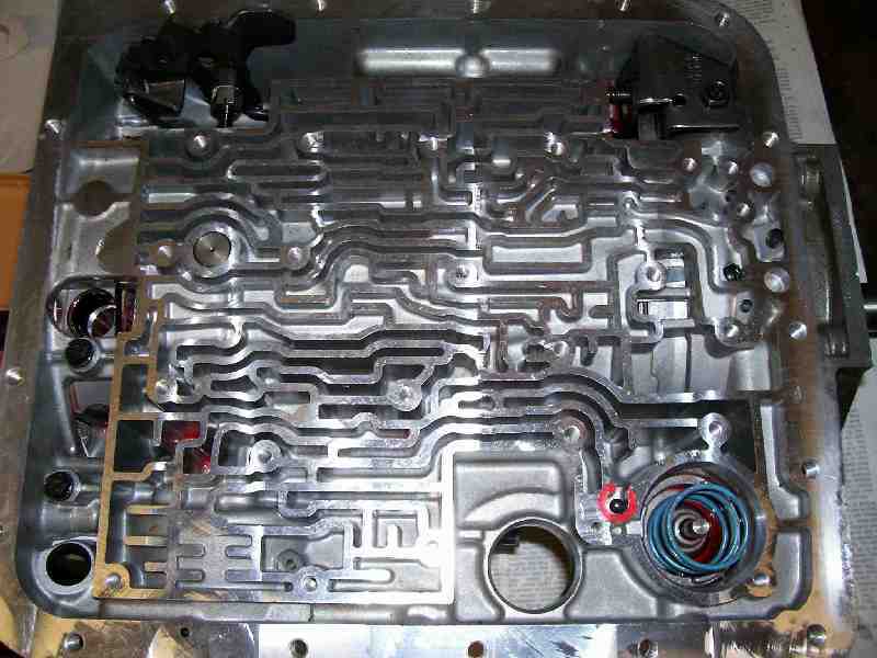
Compress
the pump pressure relief valve cap inward slightly against the springs,
then remove the valve snap ring.
Remove the valve body, reverse
boost spool, both
springs,
and internal pressure control/regulator valve spool. The
entire pressure control and boost valve can be left in place
until the pump is removed, but removing it now will allow more oil to
drain out while the bench is already full of contaminated oil.
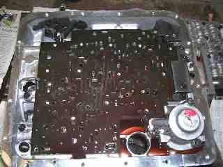
Remove
the valve body bolts and the lower valve body. Secure the work
area so
that all seven of the check balls will be contained when removing the
plate. Take care to release the lower separator plate
gasket. Even if
you plan to replace the gasket, it will be easier to remove the gasket
in one piece than to clean off all remnants of the gasket from the
valve body or separator plate.
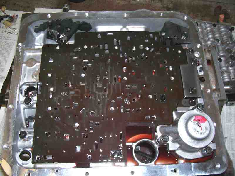
Remove the 2nd gear accumulator bolts
and accumulator.
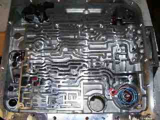
Remove
the three bolts from the stamped steel plate near the left rear corner
of the valve body, remove the three accumulator body bolts, then
remove the separator plate. There will be at least one additional
check ball to capture when the plate is removed. The second check
ball
in the upper valve body should be retained in a cage assembly, but may
be loose. With the separator plate removed, remove the accumulator
spring.
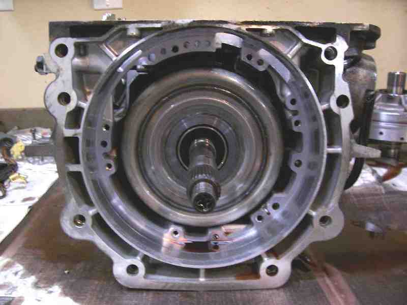
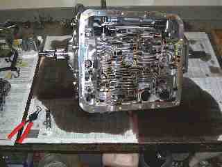
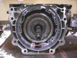
Remove
the pump housing bolts and carefully pry the pump out of the front of
the case. There are pump pullers designed specifically for this
purpose, but a careful use of a large flat bar will coax the pump and
its sealing ring out of the front cavity bore with no damage.
Prying
between the pump and input drum and/or the gaps at the bottom of the
transmission case should get it moving forward. Be careful to avoid
damage to the pump gasket and case machined surfaces.
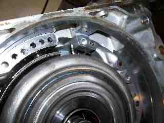
Remove
the band anchor pin from the upper valve body area. A strong
magnet
works well for this. This should relax the band adequately to
allow
removal of the reverse input drum assembly.
On the exterior of the right side of
the transmission case, clean the area surrounding the 2-4 band servo
cover. Compress the outer cover for the 2-4 servo inward, then
remove
the lock ring. Slide the cover and servo assembly outward.
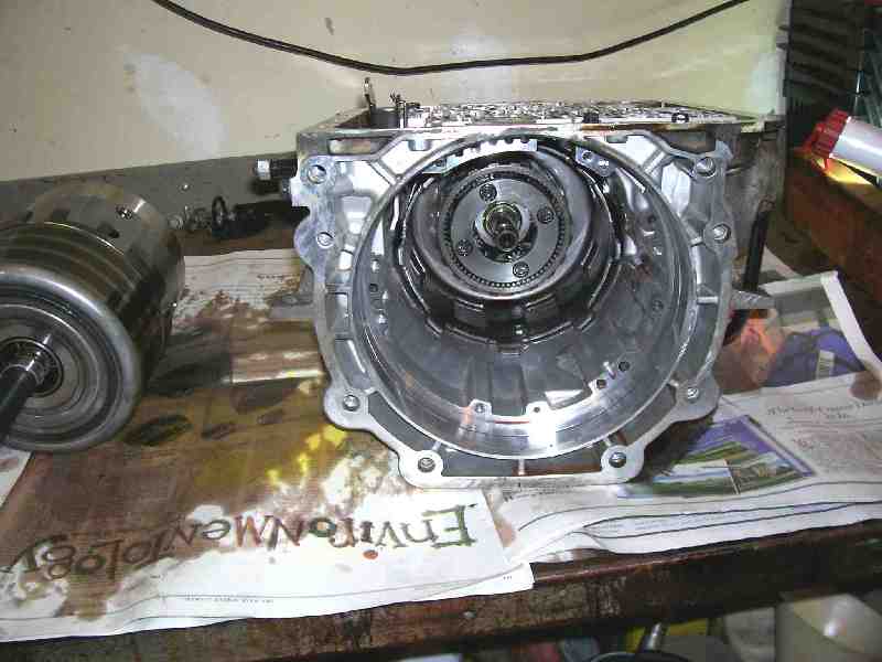
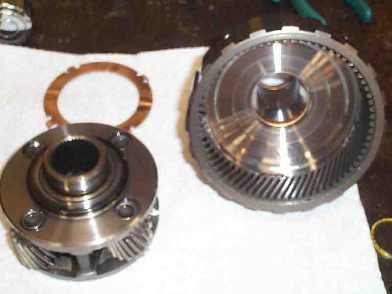
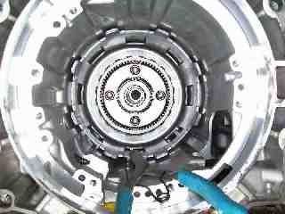
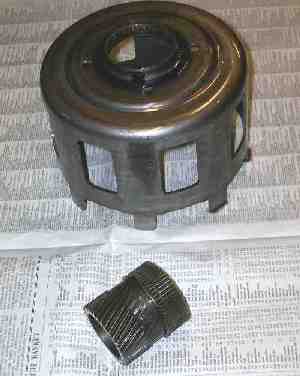
Remove the input shell and drum/clutch assembly. Pull straight outward
and support the weight of the assembly as it disengages from the
reaction shell and input planetary set.
Remove the band. These parts should now be sitting on the bench:
Remove
the yellow shaft lock retaining ring from the output shaft, then remove
the input sun gear. You should also be able to remove the VSS or
speedometer thimble, tail shaft housing (if equipped), and output shaft
at this time.

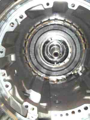
Remove
the input planetary set as an assembly.
Remove
the reaction sun shell. There is a thrust washer visible on the
front,
and another behind the shell which should be attached to the reverse
sprag hub. Be aware that it may fall out as you remove the shell
and
that this is no cause for alarm.
This reaction sun gear spline had lost the rear retaining ring from the
groove and showed some spline damage - The spline does not fit new sun
shell hub easily.
Remove
the large lock ring holding the low-reverse clutch support, then lift
out the support plate. There is no spring force behind the
support, so
the lock ring should disengage easily.
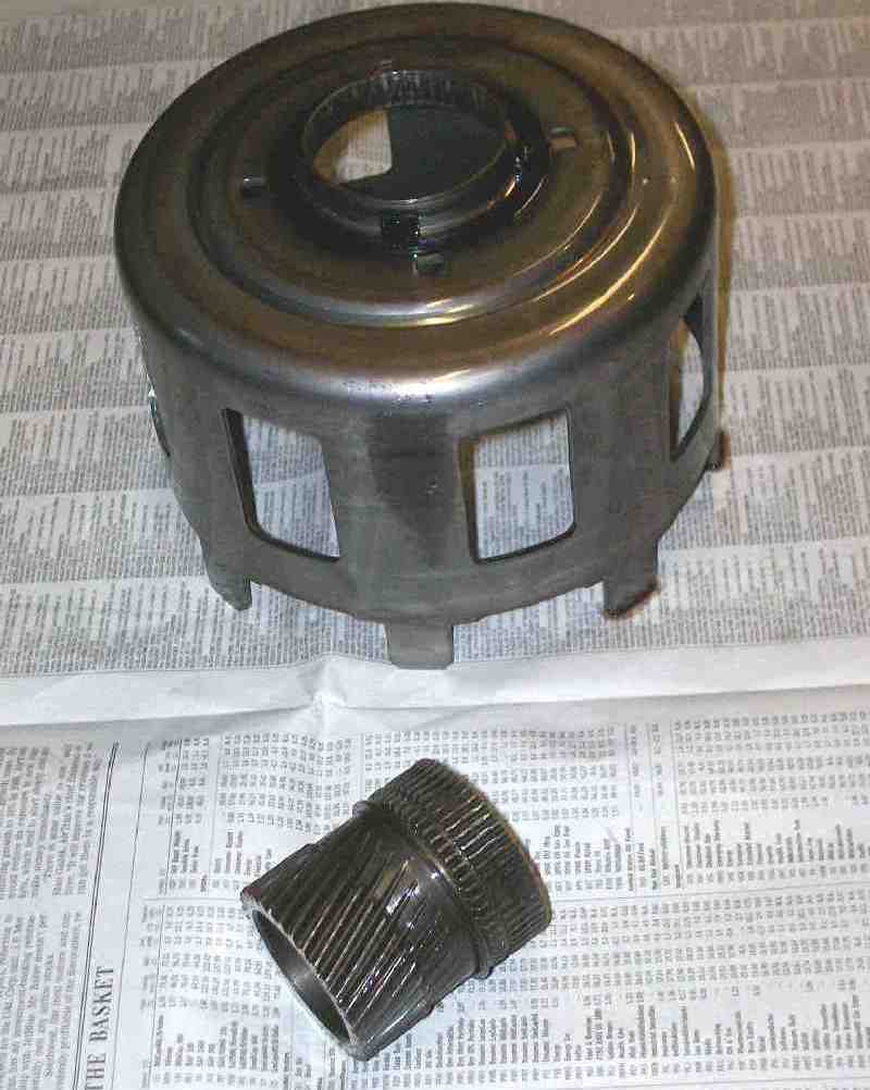
Remove the low-reverse (reaction)
planetary assembly as a unit.
Remove the low-reverse clutch stack
and low-reverse planetary ring gear, then the support plate behind
that. Remove the planetary ring gear support lock ring.
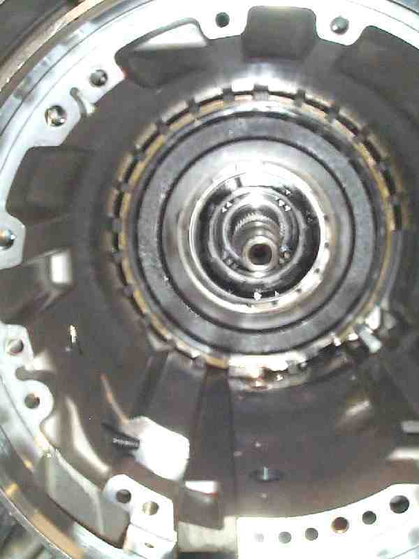
You should now be looking at the
low-reverse clutch apply assembly. Compress the low-reverse clutch
spring pack with a suitable tool, then remove the retaining ring from
the hub. Relax the compression on the spring pack and remove all
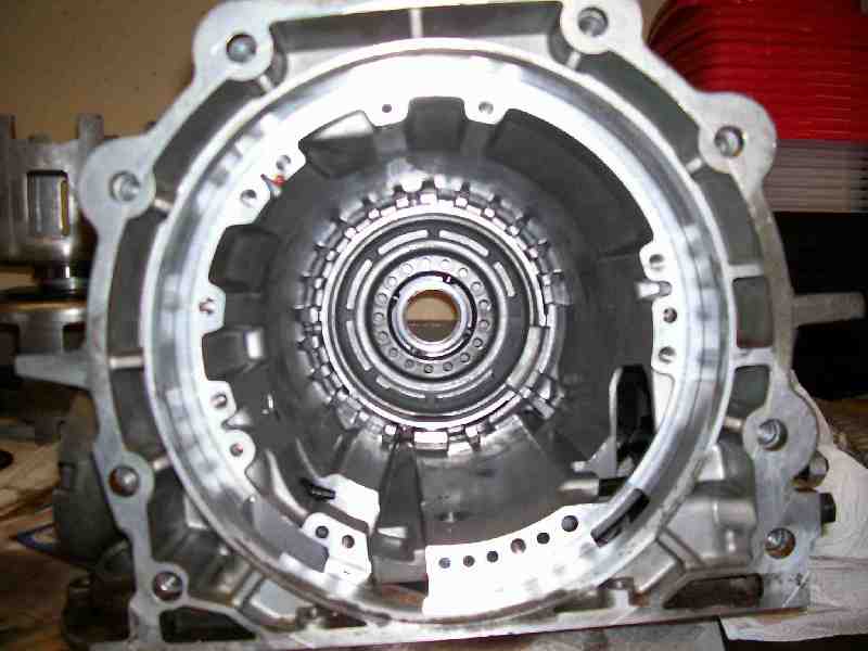
the
parts. The case should now be essentially a bare casting, other than
some seal rings, bushings, and the parking pawl and shift linkage
remaining in the case. This is an appropriate time to clean the
case
exterior thoroughly in preparation for assembly.